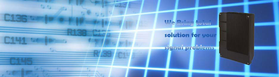
 Mobile Signal Booster
- GSM Series: UNIG3 (GSM 850MHz) | UNIG6 (GSM 900MHz) | UNIG8 (GSM 1800MHz) | UNIG9 (GSM 1900MHz)
- CDMA Series: UNIC1 (CDMA 450MHz) | UNIC3 (CDMA 800MHz) | UNIC9 (CDMA 1900MHz)
- WCDMA: UNIW5 (WCDMA 2100MHz) | UNIW3 (WCDMA 850MHz) | UNIW9 (WCDMA 1900MHz)
- LTE: UNIL2 (LTE 700MHz) | UNIL8 (LTE 1800) | UNIL9 (LTE 1900MHz) | UNIL7 (LTE 2600MHz)
- IDEN: UNII3 (IDEN 800MHZ)
Description
 Digital ICS Repeater (Interference Cancellation System) is a new kind of RF Repeater that can automatically detect and cancel the interference signal caused by oscillation of RF feedback between the Donor and Services Antennas in real time by adopting DSP (Digital Signal Processing) technology, which restores full operational capability against multi-path fading cellular signals and feedback signals by oneself and all types of waveforms from both friendly and intentional sources of interference.
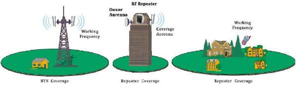
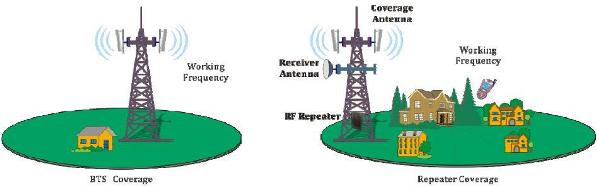
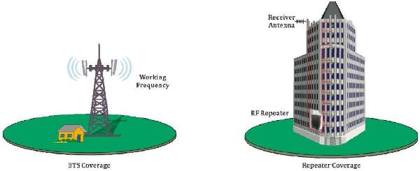
Same to RF Repeater, the Digital ICS Repeater is working as a relay between the BTS and mobiles. It picks up the cellular signal from the BTS via the Donor Antenna, linearly amplifies the cellular signal and then retransmits it via the Services Antenna to the weak/blind coverage area. And the mobile signal is also amplified and retransmitted to the BTS via the opposite direction.
As per operator's requirement for working frequency, two types of ICS repeater are available:
- Band Selective ICS Repeater: to amplify all signals in the whole band (Various bandwidth is available upon request)
- Channel Selective ICS Repeater: to amplify only the signals transmitted by the customized 1 or 2 or 4 or 6 or 8 or 12 channel (A narrow band with customized central frequency)
Features
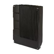
- Aluminum-alloy casing with IP65 protection and compact design, cool system without fan
- Real-time cancellation of interference signal (incl. multi-path fading, feedback signal)
- ICS function to prevent self-oscillation, enhance gain and coverage range and reduce isolation requirement
- In-built AGC & ALC function be able to ensure easy installation without setting
- Unique max AGC60dB firmware to ensure stable operating on moving platforms such as ship or trains
- Compact size and light weight, easy to install on wall or pole
- High working gain as Min. 90dB
- Output power +30dBm - +43dBm for large coverage application
- Filter with highly selectivity and low insertion loss eliminates interference between uplink and downlink
- Built-in wireless modem (Option) for remote monitoring by SMS
- Details repeater parameters and status can be monitored by software
- High gain linear power amplifier technique with reliable performance
Application
- Outdoor/Rural: Airports, Tourism Regions, Golf Courses, Tunnels, Factories, Mining Districts, Villages, ……
- Indoor: Hotels, Exhibition Centers, Basements, Shopping Malls, Offices, Packing Lots, ……
The ICS Repeater is mainly applicable to such cases:
- The repeater can find an installation place which can receive pure BTS signal at strong enough level as the Rx Level in repeater site should be more than -70dBm;
- And the isolation requirement is hard to meet by using a RF Repeater.
Digital ICS Repeater installed on top of building for Outdoor Coverage
Digital ICS Repeater installed on tower for Outdoor Coverage
Digital ICS Repeater installed for Inbuilding Solution
Specification
| Specifications | ||
|---|---|---|
| Working Frequency (customizable) | Uplink | 452.5~457.5MHz / 806~824MHz/824~849MHz / 890~915MHz / 1710~1785MHz / 1895~1910MHz |
| Downlink | 462.5~467.5MHz / 851~869MHz/869~894MHz / 935~960MHz / 1805~1880MHz / 1975~1990MHz | |
| Working Bandwidth | 2~25 MHz (customizable) | |
| Output Power (customizable) | 27~43 dBm (0.5~20 W) | |
| Gain | ≥ 90dB | |
| Gain Adjustment Range | 1~31dB @ step of 1dB | |
| Voltage Standing Wave Ratio (VSWR) | < 1.4 | |
| Noise Figure | ≤ 4dB | |
| In-Band Ripple | ≤ 3dB p-p | |
| Operating Maximum Gain | ≥Antenna Isolation + 10dB | |
| Power Amplifier Oscillation Protection | Interference Cancellation System | |
| Interference Cancellation Range | ≥ 25dB | |
| Cancellation Feedback Signals – Maximum Sizes of Window | ≥ 6μSec | |
| Spurious Emission | Within working band | ≤ -15dBm/30kHz |
| Out of working band (Δf > 2.5MHz) |
9kHz~1GHz: ≤ -36dBm/30kHz | |
| 1GHz~12.75GHz: ≤ -30dBm/30kHz | ||
| In-Band Intermodulation Attenuation | ≤ -40dBc/30kHz (measured under rated output power) | |
| System Delay | ≤ 5μSec | |
| I/O Impedance | 50Ω | |
| RF Connector | N-Type (Female) | |
| Temperature Range | Operation: -25°C ~ +55°C / Storage: -30°C ~ +60°C | |
| Relative Humidity Range | ≤ 95% (non condensing) | |
| Power Supply (customizable) | DC +24V / AC 220V±15%, 50Hz / AC 110V±15%, 50Hz | |
| Backup Power Supply (optional) | 4 hours | |
| Casing Level | Output power @27~30dBm: IP31 Output power @33~43dBm: IP65 |
|
| Dimensions | Output power @27~30dBm: 385mm X 300mm X 130mm Output power @33~37dBm: 570mm X 325mm X 215mm Output power @37~43dBm: 610mm X 445mm X 215mm |
|
| Weight | Output power @27~30dBm: 8kg Output power @33~37dBm: 27kg Output power @37~43dBm: 35kg |
|