 Mobile Signal Booster
- CDMA 450M: UNRC1
Description
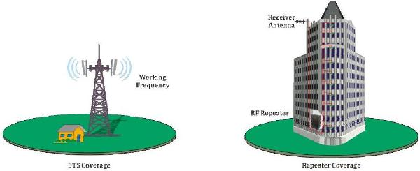
 CDMA 450M RF Repeater is designed to solve problems of weak mobile cellular signal, which is much cheaper than adding a new Base Station (BTS). Main operation of RF Repeaters system is to receive low-power cellular signal from BTS via radio frequency (RF) transmission and then transmit the amplified signal to the areas where network coverage is inadequate. And the mobile signal is also amplified and transmitted to the BTS via the opposite direction.
According to your requirement for working frequency, you can choose either type of RF Repeaters:
- Band Selective RF Repeaters System: to amplify all signals in the whole band (Various bandwidth is available upon request)
- Wireless Channelized RF Repeaters System: to amplify only the signals transmitted by the customized 1 or 2 or 4 or 6 or 8 channel (A narrow band with customized central frequency)
Application
To expand signal coverage of fill signal blind area where signal is weak or unavailable.
- Outdoor/Rural: Airports, Tourism Regions, Golf Courses, Tunnels, Factories, Mining Districts, Villages etc.
- Indoor: Hotels, Exhibition Centers, Basements, Shopping Malls, Offices, Packing Lots etc
- The repeater can find an installation place which can receive pure BTS signal at strong enough level as the Rx Level in repeater site should be more than -70dBm;
- And can meet the requirement of antenna isolation to avoid self-oscillation.
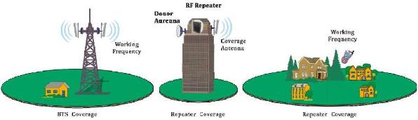
CDMA 450M Repeater installed on top of building for Outdoor Coverage
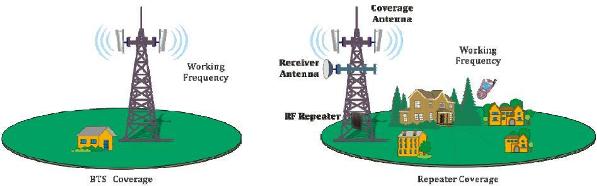
CDMA 450M Repeater installed on tower for Outdoor Coverage
CDMA 450M Repeater installed for Inbuilding Solution
Specification
| Specifications | ||
|---|---|---|
| Working Frequency (customizable) | Uplink | 452.5~457.5MHz |
| Downlink | 462.5~467.5MHz | |
| Working Bandwidth | 5 MHz (customizable) | |
| Output Power (customizable) | 27~43 dBm (0.5~20 W) | |
| Gain | ≥ 85dB | |
| Gain Adjustment Range | 1~31dB @ step of 1dB | |
| Voltage Standing Wave Ratio (VSWR) | < 1.5 | |
| Noise Figure | ≤ 5dB | |
| In-Band Ripple | ≤ 3dB p-p | |
| Max. Input Level | ≥ -10dBm | |
| Spurious Emission | Within working band | ≤ -15dBm/30kHz |
| Out of working band (Δf > 2.5MHz) |
9kHz~1GHz: ≤ -36dBm/30kHz | |
| 1GHz~12.75GHz: ≤ -30dBm/30kHz | ||
| In-Band Intermodulation Attenuation | ≤ -40dBc/30kHz (measured under rated output power) | |
| System Delay | ≤ 1.5μSec | |
| I/O Impedance | 50Ω | |
| RF Connector | N-Type (Female) | |
| Temperature Range | Operation: -25°C ~ +55°C / Storage: -30°C ~ +60°C | |
| Relative Humidity Range | ≤ 95% (non condensing) | |
| Power Supply (customizable) | DC +24V / AC 220V±15%, 50Hz / AC 110V±15%, 50Hz | |
| Backup Power Supply (optional) | 4 hours | |
| Casing Level | Output power @27~30dBm: IP31 Output power @33~43dBm: IP65 |
|
| Dimensions | Output power @27~30dBm: 385mm X 300mm X 130mm Output power @33~37dBm: 570mm X 325mm X 215mm Output power @37~43dBm: 630mm X 400mm X 230mm |
|
| Weight | Output power @27~30dBm: 8kg Output power @33~37dBm: 27kg Output power @37~43dBm: 35kg |
|
| Remote Monitoring/Control via NMS | Supported | |
| AGC (Automatic Gain Control) / ALC (Automatic Level Control) |
Supported | |